
2026-08-22
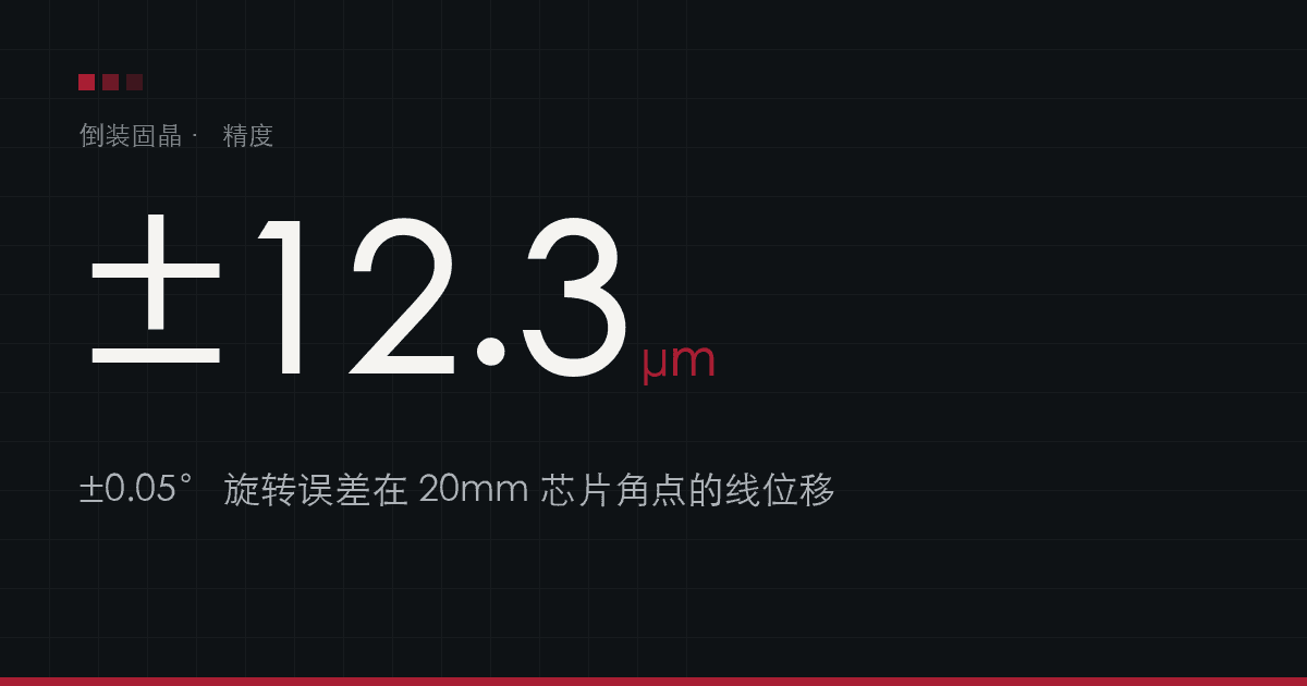
±0.05° means ±12μm on a 20mm die: the rotation spec that gets overlooked
Die attach datasheets normally list accuracy like this:
XY placement accuracy ±5μm @3σ
Rotation accuracy ±0.05° @3σ
Two lines side by side, reading as two independent figures. On a large die the second one can matter more than the first.
How angular error becomes displacement
When a die rotates about its centre, points further from the centre move further. The furthest points are the corners.
For a square die of edge length L, the corner sits L/2 × √2 from the centre. A rotation of θ degrees produces a linear displacement of approximately:
displacement ≈ (L/2 × √2) × θ × π / 180
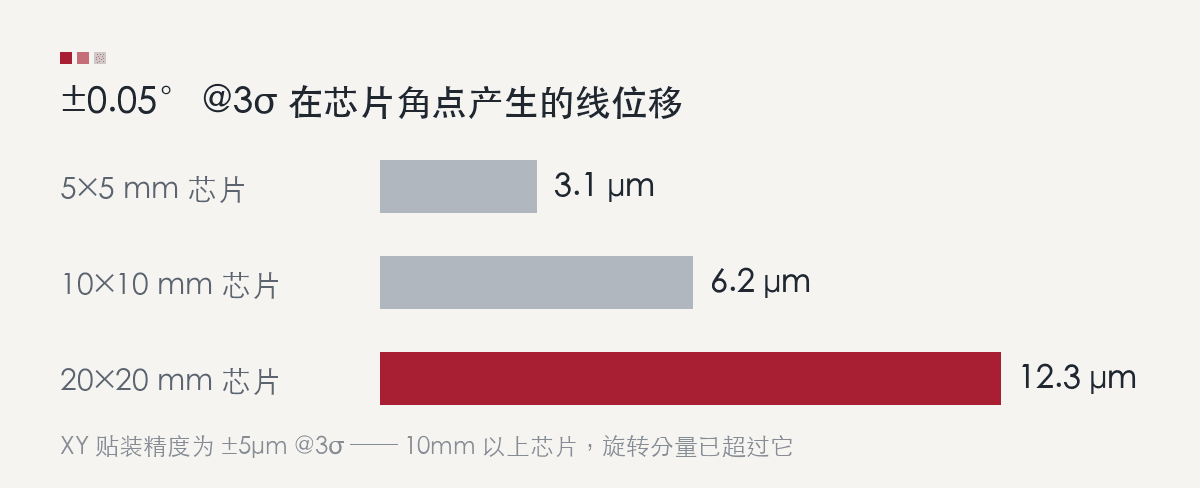
| Die size | Corner displacement at ±0.05° | Against ±5μm XY |
|---|---|---|
| 5×5 mm | ±3.1 μm | below the XY error |
| 10×10 mm | ±6.2 μm | already exceeds it |
| 20×20 mm | ±12.3 μm | 2.5× the XY error |
Why it matters
Flip-chip assembly aligns bumps on the die to pads on the substrate. What determines pass or fail is bump-to-pad offset, not the position of the die centre.
The outermost bumps sit furthest from the die centre and are therefore most affected by rotation. In other words, yield is governed by corner displacement, not by the XY number on the first line of the datasheet.
The finer the bump pitch, the sharper this becomes. Once pitch tightens into the tens of microns, a corner offset in the low teens consumes the alignment window on its own.
How to work it out during selection
- Convert the theta spec into corner displacement using your largest die size
- Combine it with the XY figure as a vector sum to get total corner offset
- Compare that against the alignment window your bump pitch allows
For example: ±5μm XY plus a ±12.3μm rotation component on a 20mm die gives roughly ±13.3μm total at the corner. If the bump pitch tolerates ±15μm, only 1.7μm of margin remains for substrate tolerance, thermal distortion and incoming material variation.
Easy to miss on a datasheet
- The die size used to measure theta — measured on a small die the number looks better but says little about large-die behaviour
- Whether it is @3σ — as with XY, an angular figure without a statistical basis cannot be used in a yield model
- Whether vision covers the corners — a system that images only the die centre cannot detect rotation error
D-MARS FC
Our flip-chip die bonder places at ±5μm @3σ with ±0.05° @3σ rotation, at 6,000 UPH, with up to 5,000g bond force and optional carrier and head heating.
The arithmetic above applies to any vendor's tool. If you are comparing flip-chip bonders, send us the theta specs of the candidates along with your largest die size and bump pitch, and we can help work through the margin analysis.