
2026-08-20
Die attach cycle time in panel-level packaging: how long does one 600×600mm panel take?
The case for panel-level packaging starts with area. A 300mm wafer offers about 70,686 mm² of usable surface. A 600×600mm panel offers 360,000 mm² — more than five times as much, with none of the unusable crescent around a round edge. The same tools and the same process pass are spread across many more packages.
The first thing that changes at die attach is not accuracy. It is count.
Smaller die, more placements per panel
Placement count is set by package pitch — die size plus the spacing the fan-out routing requires. Halve the pitch and the count per panel quadruples.
| Package pitch | Placements per panel |
|---|---|
| 3 mm | 40,000 |
| 4 mm | 22,500 |
| 5 mm | 14,400 |
| 8 mm | 5,625 |
| 10 mm | 3,600 |
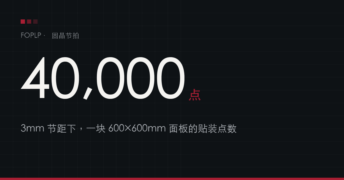
A 2×2mm die with its fan-out area typically lands near a 3mm package pitch. That means forty thousand placements per panel.
How long forty thousand placements take
Divide the count by UPH to get die attach time per panel:
| Pitch / count | 10K UPH | 20K UPH | 40K UPH |
|---|---|---|---|
| 3 mm / 40,000 | 4.00 h | 2.00 h | 1.00 h |
| 4 mm / 22,500 | 2.25 h | 1.12 h | 34 min |
| 5 mm / 14,400 | 1.44 h | 43 min | 22 min |
| 8 mm / 5,625 | 34 min | 17 min | 8 min |
| 10 mm / 3,600 | 22 min | 11 min | 5 min |
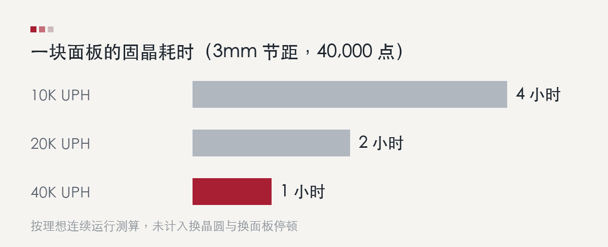
For large packages the differences are measured in minutes and rarely govern the line. For small die they are not: at 3mm pitch, 10K versus 40K UPH is four hours versus one hour per panel.
What that means for the line
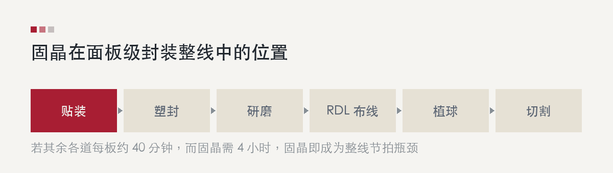
Die attach does not run in isolation. A panel passes through placement, moulding, grinding, RDL, ball mount and singulation. If the other steps take roughly 40 minutes per panel and die attach takes four hours, die attach sets the line cadence.
Keeping the line in step then means adding die attach tools:
- 3mm pitch at 10K UPH: 4 hours per panel, roughly 6 tools to match the line
- 3mm pitch at 40K UPH: 1 hour per panel, roughly 1.5 tools
Tool count translates directly into capital cost, cleanroom floor area, spare parts inventory and maintenance headcount. For a small-die product line, UPH is not only a performance figure — it shapes the capital structure of the line.
These figures assume ideal continuous operation. Real scheduling must also account for wafer change, panel change and alignment verification, which depend on the number of die types and the material handling scheme.
Ways to raise the rate
Simply moving a single head faster runs into acceleration and settling limits. The returns are small and they are paid for in accuracy. Three approaches are practical:
- Parallel bond heads — several heads working at once, so throughput scales with head count without pushing single-head motion parameters
- Dual wafer feed — one wafer is prepared while the other is being picked, so material change does not consume placement time
- Multi-die simultaneous attach — several die placed in one pick-and-place motion, suited to dense arrays of identical die
The D-MARS 8900 combines all three: a multi-head architecture, dual 8"/12" wafer feed, and multi-die simultaneous attach, reaching 30K UPH on a 600×600mm panel.
Rate cannot come at the cost of accuracy
The accuracy requirement in panel-level packaging comes from die shift downstream.
A fan-out flow typically places bare die on a temporary carrier, moulds over them, then builds RDL on the moulded surface. Epoxy moulding compound shrinks as it cures and the die move with it. At wafer level that displacement can be absorbed by compensating the RDL exposure. On a larger panel the same shrinkage rate produces larger absolute displacement, and the direction differs between panel centre and edge, so compensation moves from a global offset to a zone-by-zone fit.
Placement error at die attach adds to that displacement. The alignment window available to RDL is fixed; the less of it die attach consumes, the more tolerance remains downstream.
Rate and accuracy therefore need to hold together rather than trade off. The D-MARS 8900 places at ±5μm @3σ with ±0.1° @3σ rotation while running at 30K UPH.
Reading the specifications
Comparing accuracy figures requires a consistent statistical basis. ±5μm and ±5μm @3σ are different statements: the second means 99.73% of placements fall within that window and can be used directly in a yield model. It is also worth confirming the die size used for measurement, whether carrier positioning error is included, and whether accuracy holds at the panel corners as well as the centre.
The same applies to UPH: confirm the die size it refers to, whether the build is single or mixed die, and whether material change is included.
Working from your own numbers
The figures above illustrate orders of magnitude. Cycle time for a specific project depends on die size, package pitch, the number of die types, wafer size and the cycle time of the surrounding process steps.
If you are evaluating die attach configuration for a panel-level line, send us your die size, target pitch and output goal. Our applications engineering team will work through the cycle time for your case, including a tool count recommendation and an analysis of where the line bottleneck falls.